What is a Main Engine Harness?
A Ve5701 Main Engine is a critical component in a vehicle’s electrical system. It consists of a bundle of wires, connectors, and terminals that interconnect the various electronic components and sensors in the engine compartment with the vehicle’s central electrical system and the engine control unit (ECU).
Role of the Main Engine Harness in a Vehicle:
- Power Distribution: The main engine harness delivers electrical power from the battery and alternator to various engine components, such as the fuel injectors, ignition coils, sensors, and actuators. This ensures that all these parts have the power they need to function correctly.
- Signal Transmission: The harness carries signals between the engine’s sensors and the ECU. These signals include data on engine temperature, oxygen levels in the exhaust, throttle position, and more. The ECU uses this information to adjust fuel delivery, ignition timing, and other engine parameters to optimize performance and efficiency.
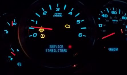
- Communication The main engine harness also allows for communication between different vehicle systems. For instance, it enables the transmission of data between the ECU and the vehicle’s dashboard, where information such as engine RPM, temperature, and check engine light status is displayed to the driver.
- Safety: The harness plays a role in safety by ensuring that critical components, like the fuel pump and ignition system, are properly powered and can function correctly. A malfunctioning harness can lead to engine performance issues, stalling, or even failure to start, which can compromise vehicle safety.
- Integration with Other Systems: In modern vehicles, the main engine harness is integrated with other vehicle systems, such as the transmission control module, anti-lock braking system (ABS), and electronic stability control (ESC). This integration allows for coordinated operation of these systems, improving overall vehicle performance and safety.
Using a stock harness with a Microsquirt ECU can present several challenges due to the differences in design and functionality between the stock engine management system and the aftermarket Microsquirt system. Here are some of the main challenges:
Discuss the challenges of using a stock harness with a Microsquirt ECU.
Wiring Compatibility
- Connector Differences: Stock harnesses are designed to work with the original ECU, which often has proprietary connectors and pin layouts. Microsquirt, being an aftermarket solution, uses different connectors and may require modifications to the stock harness to ensure compatibility.
- Pinout Mismatch: The pinout (the layout of the wires and their functions) in the stock harness is specific to the original ECU. When switching to a Microsquirt ECU, you may need to repin the connectors or use adapter harnesses to match the Microsquirt’s pinout.
Sensor and Actuator Integration
- Sensor Compatibility: The sensors used in the stock setup might have different signal types or voltage ranges compared to what the Microsquirt ECU expects. This could require the use of additional signal conditioning hardware or the replacement of certain sensors with ones that are compatible with Microsquirt.
- Actuator Control: The stock harness is wired for specific actuators, such as injectors and ignition coils, that are controlled by the stock ECU. The Microsquirt ECU may have different control methods, requiring rewiring or the addition of external driver modules to ensure proper operation.
Electrical Load Management
- Power Supply Differences: The power requirements and distribution in a stock harness are tailored to the original ECU. Microsquirt may have different power supply needs, such as separate power lines for sensors and actuators, which could necessitate modifications to the stock harness to provide stable and appropriate power.
- Grounding Issues: Proper grounding is crucial for reliable ECU operation. The stock harness may not provide sufficient or appropriate grounding for the Microsquirt system, leading to electrical noise or unreliable sensor readings. Additional grounding points may need to be added.
Engine Functionality
- Limited Support for Stock Features: Microsquirt is a versatile but simplified ECU compared to many OEM ECUs, which are often designed to control a wide range of functions beyond just the engine, such as transmission control, emissions systems, and advanced driver-assistance systems (ADAS). Integrating Microsquirt into a system with these functions may require disabling certain features or finding workarounds.
- Calibration and Tuning: The stock ECU is pre-calibrated for the specific engine configuration, while Microsquirt requires custom tuning. The stock harness might limit your ability to easily connect tuning devices or diagnostic tools, complicating the tuning process.
Installation and Customization
- Physical Installation: Adapting the stock harness to work with the Microsquirt ECU might require physical modifications to the harness, such as extending wires, adding new connectors, or splicing in additional circuits. This can be time-consuming and requires careful planning to avoid damaging the harness.
- Customization Needs: Depending on the vehicle and engine setup, the stock harness may not have all the necessary connections for the features you want to use with Microsquirt, such as additional sensors or auxiliary outputs. Customizing the harness to add these features can add complexity to the installation.
instructions on modifying or building a custom harness.
Creating or modifying a custom engine harness for use with a Microsquirt ECU involves several steps. Here’s a step-by-step guide to help you through the process:
Step 1: Planning and Preparation
- Gather Information: Obtain the pinout diagrams for both the stock harness and the Microsquirt ECU. This will help you understand how the wires need to be connected and what modifications are necessary. Identify the functions of each wire in the stock harness and compare them with the requirements of the Microsquirt ECU.
- Design the Wiring Layout: Create a schematic or diagram of how you plan to rewire the harness. This should include connections between the Microsquirt ECU and engine components such as sensors, actuators, and power sources.
- Gather Materials and Tools: Materials: Wiring (appropriate gauge), connectors, terminals, heat shrink tubing, electrical tape, and any necessary adapter plugs or pins. Tools: Wire stripper, crimping tool, soldering iron, multimeter, and possibly a wiring diagram software for detailed schematics.
Step 2: Disassemble the Stock Harness
- Remove the Stock Harness: Carefully disconnect the stock harness from the engine and the ECU. Take note of how the harness is routed and attached to the vehicle.
- Label and Document: Label each wire in the stock harness according to its function. This will help you when you are making connections to the Microsquirt ECU. Document the connections and pin locations for future reference.
Step 3: Modify or Build the Custom Harness
- Prepare Wires and Connectors: Cut and strip the wires to the appropriate lengths. Ensure you use the correct gauge of wire for each connection to handle the current load. Crimp or solder connectors to the ends of the wires as needed.
- Create Custom Connections: For each wire in the stock harness, match it to the corresponding pin on the Microsquirt ECU. This may require repinning connectors or creating new connectors. Use the pinout diagrams to ensure correct wiring.
- Handle Power and Grounding: Ensure that the power and ground wires are correctly routed and connected. The Microsquirt ECU will have specific requirements for power supply and grounding that may differ from the stock setup. Add additional ground wires if necessary to ensure proper operation of the ECU.
- Integrate Sensors and Actuators:Connect the engine sensors and actuators to the Microsquirt ECU according to the new wiring layout. This includes components like fuel injectors, ignition coils, and temperature sensors.Use the appropriate connectors and ensure that all connections are secure and properly insulated.
Step 4: Testing and Validation
Check Continuity and Connections:
- Use a multimeter to check continuity and verify that all connections are correct and not shorted or open. This helps identify any wiring issues before powering up the system.
Power Up the System:
- Connect the battery and power up the Microsquirt ECU. Verify that the ECU powers on and that there are no error codes or issues with the initial startup.
Test Functionality:
- Check that all sensors and actuators are functioning correctly with the Microsquirt ECU. Ensure that the engine starts and runs smoothly, and monitor any diagnostics or error codes.
Adjust and Fine-Tune:
- Make any necessary adjustments to the wiring or connections based on the test results. Fine-tune the ECU settings and perform any required calibration or tuning to ensure optimal engine performance.
Step 5: Finalizing and Securing
Secure the Harness:
- Once testing is complete, secure the custom harness in place using cable ties or clamps. Ensure that the wiring is protected from heat, vibration, and abrasion.
Insulate and Protect:
- Use heat shrink tubing, electrical tape, or conduit to protect the wires and connectors. This will help prevent damage and ensure long-term reliability.
Reassemble the Engine Bay:
- Reinstall any components or covers that were removed during the harness modification process. Ensure that everything is properly reassembled and secured.
By following these steps, you can successfully modify or build a custom harness for your Microsquirt ECU, ensuring proper integration and functionality with your engine components.
Offer tips on wire selection, connectors, and routing.
When building or modifying an engine harness, careful attention to wire selection, connectors, and routing is crucial for ensuring reliability and performance. Here are some tips to guide you through these aspects:
Wire Selection
Wire Gauge:
- Choose the Right Gauge: Use the appropriate wire gauge for each circuit based on the current it needs to carry. For instance, high-current wires for power distribution (e.g., fuel pump, ignition) should be thicker (lower gauge) than low-current wires for signal transmission.
- Refer to Specifications: Consult the specifications for the components you’re connecting to determine the correct wire gauge. Typically, 16-18 gauge is used for most signal wires, while 12-14 gauge is used for high-current applications.
Wire Insulation:
- Select Quality Insulation: Use wires with insulation rated for automotive use, such as PVC, Teflon, or silicone rubber. This insulation should be heat-resistant, flexible, and durable to withstand the engine bay environment.
- Consider Temperature Ratings: Ensure the wire insulation can handle the temperature extremes in the engine bay.
Wire Color Coding:
- Use Consistent Colors: Employ a consistent color-coding scheme to make it easier to identify wires and troubleshoot issues. For example, use red for power, black for ground, and other colors for specific signals.
Connectors
Connector Types:
- Choose Appropriate Connectors: Select connectors that are durable and reliable for automotive use. Common types include weatherproof connectors for engine bay applications and simple crimp connectors for less demanding areas.
- Use Quality Connectors: High-quality connectors prevent issues such as corrosion and poor connections. Ensure they have proper sealing to protect against moisture and dirt.
Crimping and Soldering:
- Crimp Securely: Use a proper crimping tool to ensure secure connections between wires and terminals. Poor crimping can lead to intermittent connections and electrical issues.
- Solder When Necessary: For critical connections, especially where vibration or movement is a factor, consider soldering connections to enhance reliability. However, ensure solder joints are well-insulated and protected from potential damage.
Connector Maintenance:
- Use Dielectric Grease: Apply dielectric grease to connectors to prevent corrosion and improve connectivity. This is particularly important in harsh environments like the engine bay.
Routing
Wire Routing:
- Avoid Heat Sources: Route wires away from heat sources such as the exhaust manifold and engine block. Use heat shields or insulation where wires must pass near hot components.
- Prevent Vibration Damage: Secure wires to prevent movement that can cause abrasion or wear. Use cable ties, clips, or brackets to keep the wiring neat and in place.
Protecting Wires:
- Use Conduit and Looms: Protect wires from abrasion, heat, and chemicals by using protective conduits or looms. This helps ensure long-term reliability.
- Insulate Wires: Apply heat shrink tubing or electrical tape to exposed or vulnerable areas of wires to protect them from damage.
Avoiding Interference:
- Separate Power and Signal Wires: Keep high-current power wires separated from low-current signal wires to avoid electrical interference. This minimizes the risk of noise affecting sensitive signals.
- Use Grounding Strategies: Ensure that all ground wires are properly connected to a common ground point. Poor grounding can cause electrical issues and affect performance.
By carefully selecting the right wire gauge and insulation, choosing high-quality connectors, and following proper routing and protection practices, you can build or modify a custom engine harness that is reliable, durable, and well-suited for your vehicle’s needs.
Proper attention to these details will help ensure that your harness performs optimally and withstands the demanding conditions of the engine bay.
diagrams and pinouts for specific engine and Microsquirt configurations.
To provide detailed wiring diagrams and pinouts for specific engine and Microsquirt configurations, it’s essential to have accurate information about the engine model, the Microsquirt ECU version, and any modifications or components involved.
Since detailed pinout and wiring diagrams can be specific to different configurations, I’ll outline the general approach to creating and understanding these diagrams and how you can find or create them for your setup.
Understanding Wiring Diagrams and Pinouts
Microsquirt ECU Pinout
The Microsquirt ECU pinout varies slightly depending on the version, but generally includes connections for:
- Power Supply: Battery +12V, Ground.
- Inputs: Various sensors such as coolant temperature, air temperature, and throttle position.
- Outputs: Fuel injectors, ignition coils, idle control, and possibly auxiliary outputs.
- Communication: Serial communication ports for tuning and diagnostics.
You can usually find the pinout diagram for the Microsquirt ECU in its official manual or on the Microsquirt website. Here’s a basic outline:
- Pin 1-4: Power (+12V, Ground)
- Pin 5-6: Tachometer, RPM signal
- Pin 7-10: Injector outputs
- Pin 11-12: Ignition outputs
- Pin 13-14: Analog inputs (e.g., MAP sensor, temperature sensors)
- Pin 15-16: Auxiliary outputs
- Stock Engine Harness Pinout
The stock engine harness pinout will vary by engine and vehicle model but typically includes connections for:
- Power Supply: Battery +12V, Ground.
- Sensors: Engine temperature, oxygen sensors, mass airflow, crank position.
- Actuators: Fuel injectors, ignition coils, idle control valve.
- Creating Wiring Diagrams
- Gather Information
- Engine and Microsquirt Documentation: Collect the wiring diagrams and pinouts for both the stock engine harness and the Microsquirt ECU. These can be found in the service manuals for your engine and in the Microsquirt installation guide.
- Identify Connections: Determine which wires in the stock harness correspond to the sensors, actuators, and power connections that will be used with the Microsquirt.
- Draw Wiring Diagrams
- Create a Basic Diagram: Start by drawing a basic layout of the Microsquirt ECU and the components you need to connect, such as sensors and actuators.
- Match Pinouts: Use the pinout diagrams to match the pins on the Microsquirt ECU to the appropriate wires in the stock harness. Clearly label each connection on the diagram.
- Label and Annotate: Include labels for wire colors, connector types, and any notes about special wiring requirements or modifications needed.
- Use Software Tools
- Wiring Diagram Software: Tools like Microsoft Visio, AutoCAD Electrical, or specialized automotive wiring software can be used to create precise diagrams.
- Diagram Templates: Some communities and forums provide templates for common engine and ECU setups, which can serve as a starting point.
- Example Wiring Diagram
Here’s a simplified example of what a wiring diagram might include:
Microsquirt to Engine Wiring
- Microsquirt Pin 1 (12V Power)
- Connects to the battery +12V wire in the stock harness.
- Microsquirt Pin 2 (Ground)
- Connects to a ground point in the engine bay, ensuring a clean and solid ground connection.
- Microsquirt Pin 3 (Injector 1 Output)
- Connects to the first fuel injector in the stock harness.
- Microsquirt Pin 4 (Ignition Coil 1 Output)
- Connects to the first ignition coil in the stock harness.
- Microsquirt Pin 5 (RPM Signal Input)
- Connects to the crank position sensor or tachometer signal wire in the stock harness.
- Finding Specific Diagrams
- Official Documentation: Check the Microsquirt website or contact the manufacturer for detailed diagrams specific to your ECU version.
- Automotive Forums: Enthusiast forums for your vehicle model may have user-shared diagrams and wiring tips.
- Service Manuals: Obtain the service manual for your engine, which often includes detailed wiring diagrams.
Address potential issues and troubleshooting.
When working with a custom engine harness and Microsquirt ECU, you may encounter various issues. Addressing potential problems early can prevent costly repairs and ensure smooth operation. Here’s a guide to common issues and troubleshooting tips:
Power Issues
Potential Problems:
- No Power to ECU: The Microsquirt ECU may not power on if there’s an issue with the power supply.
- Intermittent Power Loss: Power might cut out intermittently, causing engine performance issues.
Troubleshooting Tips:
- Check Wiring: Ensure that all power connections are secure and properly connected to the battery and ground.
- Inspect Fuses: Verify that all fuses related to the ECU and engine management are intact and functioning.
- Measure Voltage: Use a multimeter to check that the ECU is receiving the correct voltage (typically +12V) and that the ground is properly connected.
Signal Issues
Potential Problems:
- Incorrect Sensor Readings: Sensors might provide inaccurate data if wired incorrectly or malfunctioning.
- No Signal to ECU: The ECU may not receive signals from sensors or actuators.
Troubleshooting Tips:
- Verify Connections: Ensure that sensor wires are connected to the correct pins on the ECU and that connections are secure.
- Test Sensors: Use a multimeter or oscilloscope to test the output from sensors and ensure they are functioning correctly.
- Check Wiring: Inspect the wiring for any damage or shorts that might affect signal transmission.
Injector and Ignition Issues
Potential Problems:
- No Fuel Delivery: Injectors might not fire, causing the engine to not start or run poorly.
- Ignition Problems: Ignition coils may not fire, resulting in a no-start condition or misfires.
Troubleshooting Tips:
- Inspect Wiring: Check the wiring to the injectors and ignition coils for proper connections and integrity.
- Test Outputs: Use a test light or oscilloscope to ensure that the Microsquirt ECU is sending signals to the injectors and ignition coils.
- Check Grounds: Ensure that the grounds for the injectors and ignition coils are solid and properly connected.
Harness and Connector Issues
Potential Problems:
- Poor Connections: Loose or corroded connections can lead to unreliable performance.
- Connector Pinouts: Mis-wired connectors can cause incorrect functionality or failure of components.
Troubleshooting Tips:
- Inspect Connectors: Check all connectors for proper fit and condition. Ensure there is no corrosion or damage.
- Verify Pinout: Confirm that all wiring is correctly matched to the pinout diagrams for both the stock harness and the Microsquirt ECU.
- Rework Connections: Re-crimp or re-solder any connections that appear to be loose or faulty.
Engine Performance Issues
Potential Problems:
- Engine Misfires: Engine misfires or rough running can occur due to incorrect tuning or wiring issues.
- Poor Idle Quality: Idle problems may arise from improper sensor readings or control issues.
Troubleshooting Tips:
- Check Calibration: Ensure that the Microsquirt ECU is properly calibrated for your engine and its components. Review and adjust tuning settings as needed.
- Monitor Diagnostics: Use the Microsquirt software to check for error codes or diagnostic information that might indicate issues with the setup.
- Perform a Test Run: Conduct a test run to observe engine behavior and diagnose any performance issues. Make adjustments to the tuning or wiring based on the test results.
Common Wiring Problems
Potential Problems:
- Short Circuits: A short circuit can cause components to malfunction or damage the ECU.
- Open Circuits: Broken or disconnected wires can lead to non-functional components.
Troubleshooting Tips:
- Use a Multimeter: Measure resistance and continuity to detect short circuits or open circuits in the wiring.
- Inspect for Damage: Look for visible signs of damage to the wiring, such as frayed wires or broken insulation.
- Check for Interference: Ensure that wires are routed away from sources of electromagnetic interference, which can affect signal integrity.
By systematically addressing these potential issues and using troubleshooting techniques, you can diagnose and resolve problems with your custom engine harness and Microsquirt ECU setup. Regular maintenance and careful monitoring can help ensure reliable and optimal performance for your engine management system.